About the VHF Antenna
The VHF antenna is the most critical part of any boat VHF radio communication system. There is much to understand about how to select the right antenna, how to properly install it and how to fault find and troubleshoot aerial systems when the performance of your VHF radio is not as it should be. You can't communicate with other boats or shore stations or rescue authorities if your VHF radio antenna system is faulty. The VHF radio antenna is the component that radiates that VHF radio transmitter energy out. They are mounted in locations that are subject to the worst of the elements, and have to endure forces ranging from wind, vibration, water and more.
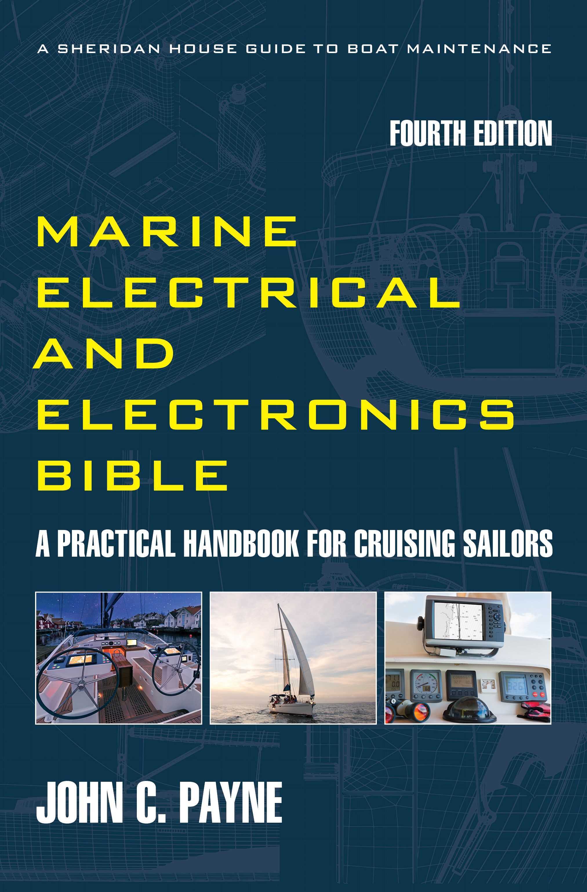
The 4th Edition of the Marine Electrical Electronics Bible Get your copy and start becoming self sufficient and save money on expensive technician callouts.
VHF Antenna Types
For a VHF antenna the majority of boats use whip aerials. Yachts often use a masthead-mounted aerial to achieve maximum height. The aerial length is directly related to the aerial gain, and the higher the gain, the narrower the transmission beam. A high gain antenna has a greater range, but during vessel rolling and pitching the lower gain antenna is more reliable with a greater coverage pattern.
Half-Wave whip aerials are typified by the stainless steel rod construction. The radiation pattern has a large vertical component, which suits boats under heel conditions. These antennae can also come in the form of a whip with lengths varying between 1 to 3 meters. The fibreglass whip effectively increases the height, and therefore the range of the radiating element, and the gain is typically 3 dB. Helical aerials have a gain slightly less at 2.5 dB, but do have a characteristically wider signal beamwidth.
The higher the gain the more directional the emitted signal becomes. Motorboats usually have 6 dB aerials as they are more directional and vessels and the aerials are normally vertical as there is roll and pitching but not a permanent heel as in sailing boats.
VHF Antenna Cables and
Connections
Cables and bad connections are the principal causes of degraded VHF antenna performance. Avoid using thin RG58U coaxial cable where possible as the attenuation is increased and large signal loss can occur. The amount of signal that gets out is dependant on low losses within the cable and the connections. For cabling aerials always use RG213/U or RG8/U 50Ω for minimum attenuation. Ensure the cable has no sharp bends that may affect the attenuation of the cable.
The typical cable attenuation of both types for a 100-foot run is as follows:
a. RG58/U. This is a nominal 7.1 dB, which is approximately a percentage signal loss of 75-80%.
b. RG8/U and RG8/X (RG213/U). This is a nominal 2.6 dB, which is approximately a percentage signal loss of 45%.
VHF Antenna Installation
Testing
Many
vessel VHF installations operate poorly, with often undiagnosed problems. Many boaters install their own cables,
connectors, and aerials, but in the majority of cases the installation is never
tested. If the maximum range is to be
realized, then the installation requires proper testing.
With the increasing reliance on digital technology, in particular, with DSC VHF units, reliability is of crucial importance. I have highlighted the importance of installing the correct coaxial cable to reduce losses. The attenuation inherent within the cable is only part of the loss equation.
Voltage Standing Wave Ratio (VSWR)
When a signal is transmitted via the cable and aerial a portion of that signal energy will be reflected back to the transmitter. The effect is that coverage is reduced due to the reduced power output. Measure the VSWR with a meter.
Up until recently you had to hire a technician to bring along an expensive meter (I am fortunate to possess a Bird meter), but also I use a simple Shakespeare meter, the ART-1. This allows easy fault diagnosis and timely repairs, and is highly commended. A number of problems can reduce the VSWR. Regular testing of reflected power and detection of excessive values will alert you to potential installation problems. It may even save your life.
VHF Antenna Installation Troubleshooting
1. Damaged or Cut Ground Shields. This is common where the cable has been jointed, or improperly terminated at the connector. Make sure the shield is properly prepared and installed.
2. Dielectric
Faults. This common problem occurs
when cables are run tightly around corners, through bulkheads, and through
cable glands. Make sure that cables are
bent with a relatively large radius, the tighter the bend, and the more
dielectric narrowing that will occur with increased reflected power.
3. Pinched Cable. This common problem occurs where a cable has
not been properly passed through a bulkhead with the gland or connector
impinging on the cable and reducing its dielectric diameter. Radio waves pass along the outside of the
central core and along the inner side of the braiding, so any deformation will
alter the inductance and reduce power output.
4. Connector Faults. The most common problem is that of connectors not being installed or assembled correctly. Ensure that connectors are properly tightened, that pins are properly inserted, and that the pin-to-cable solder joint is sound and not a dry joint. Ensure that shield seals are properly made. Many connectors appear good at the time of assembly, but deteriorate very quickly when exposed to rain, salt spray, and corrosion. Check the status with a multi-meter between the core and screen for short circuits.
5. Antenna Faults. If an antenna is out of spec or has suffered storm damage, or if a new antenna has been damaged in transit, then functional efficiency will decrease and losses increase. Inspect the antenna and connectors regularly. I always wrap the aerial connection with self-amalgamating tape to reduce ingress of moisture and salt air. More about fishing and boats and a lot more about boat radios.